Эта тема
- Везде
-
- Эта тема
- Этот форум
-
- Расширенный поиск
Поиск
Skip to main content
![]()
![]()
Welcome to EDAboard.com
Welcome to our site! EDAboard.com is an international Electronics Discussion Forum focused on EDA software, circuits, schematics, books, theory, papers, asic, pld, 8051, DSP, Network, RF, Analog Design, PCB, Service Manuals… and a whole lot more! To participate you need to register. Registration is free. Click here to register now.
-
Hardware and PCB Design
-
PCB Routing Schematic Layout software and Simulation programs
You should upgrade or use an alternative browser.
Please help me for Altium Designer
-
Thread starteraamiralikhoja
-
Start dateNov 7, 2008
- Status
- Not open for further replies.
-
#1

- Joined
- Aug 11, 2004
- Messages
- 90
- Helped
- 1
- Reputation
-
2
- Reaction score
- 1
- Trophy points
- 1,288
- Activity points
-
708
I am using altium designer summer but unable to view 3d board altium switches to 3d but only components outline is shown not actual 3d body I am using ATI CHIP SET
but using nvidia geforce graphics cad r n9500g in PCI express plase tell me what is problem. My card suport directx 10 and shadder model 4.
-
#2
Hi,
In order to see any component’s body in the 3d view, you should use components which have a PCB3D model added to them. Most of the components in the standart library of Altium doesn’t have a 3d model added by default.
Rather than creating a PCB3D model from scratch, you can also add component outlines to a mechanical layer in the PCB footprint of a component and make Altium extrude the drawing in that layer to construct the 3D representation of the component. But the representation will be of course, a simple 3d solid shape in that case.
Regards
-
#3

- Joined
- Jul 9, 2008
- Messages
- 4
- Helped
- 0
- Reputation
-
0
- Reaction score
- 0
- Trophy points
- 1,281
- Location
-
Poland
- Activity points
-
1,312
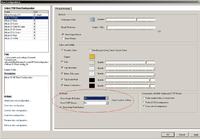
Press L in PCB editor in 3D mode, and select Yes in “show simple 3D bodies” And “STEP Models”.
Screnschot:
-
#4
- Joined
- Aug 11, 2004
- Messages
- 90
- Helped
- 1
- Reputation
-
2
- Reaction score
- 1
- Trophy points
- 1,288
- Activity points
-
708
Thanks for help are step models are included in Altium or we have to purchase sepratly
-
#5

- Joined
- Jun 26, 2007
- Messages
- 40
- Helped
- 2
- Reputation
-
4
- Reaction score
- 0
- Trophy points
- 1,286
- Activity points
-
1,597
Hi,
Can you pls help me ? Currently I want to convert one Cadence Allegro file (.brd) into Mentor Graphics (.pcb) format. I think we can do it using Altium designer where we have import Allegro brd file & save as Altium format..then export in ASCII format for PADS2005 …
I dont have altium Designer so I request you can you pls convert the file for me ??
I will be very thankful to u …
Kindly waiting for your positive reply..
Thanks in advance…
Byee !!
-
#6
I’m having the same problem in winter 09, I can’t view the PCB in 3D, nvidia geforce graphics card r 6200se Trubo, All I see is a green PCB with the outline of the components, I have used step models and aslo tried to use the manage components and put the sizes in there and still the same, I have gone into the settings has said above and ticked the boxes and restarted it but still the same, I never had this problem before I installed winter o9, I have installed the latest drivers for graphics card driver and it does support the openGL
Am I doin something wrong
should you be able to rotate the board as well ?
-
#7
should you be able to rotate the board as well ?
Yes, of course.
Btw, i want the repeat the question which is asked before:
Are these step models included in @ltium? If they are, then where are they? I wasn’t able to find any.
Regards…
-
#8
NO but you can get them from here you will have to register but the good ting that it is free
https://www.3dcontentcentral.com/default.aspx
Just download the step model drom the drop down menu, downloaf all what you need then create a new 3DPCB library then just import the step models into it, saved it then in your schematic add PCB3D the upadte well I think that is how you do it,
I can see the step model in the window Once I have gone to add PCB3D and I can rotate it, I’ve just found someting else out as well,
If I go to the Edit foot print I can only see the outline of the LCDand still can rotate it and in the litle tool box menu everything there it ticked, but in the edit PCB3D I can see full LCD and can rotate it Strange,When I select view menu and switch to 3D I cannot roate the board or see any components
-
#9
When I select view menu and switch to 3D I cannot roate the board or see any components
Are you sure that you are using the right key/mouse button combination to rotate? If you are, then it is weird because rotation has nothing to do with the drivers etc. Therefore if you can see the board, then you SHOULD be able to rotate it
I downloaded some STEP models from the site you’ve provided. I wasn’t able to see the bodies in the actual PCB during my first trial. I’m gonna try it again when i have the time and post the results here if i could make it work.
Regards…
-
#10
When I added a step model in the PCB library or through the schematic library I can see the step model and I can rotate that model, and view it in any angle, But when I’m in the PCB I click view 3D and all I see is a bare board wiht a slik screen, and when I click to move or rotate the board so you can view it in any angle it will not let me it tells me that “action is not available in 3D view “
Now when you watch the tut or demo you can see them viewing the baord in any angle ?
-
#11
I guess you’re trying to rotate by clicking and dragging with the left mouse button. That only works in library editor windows. In order to rotate the PCB in the 3d view you should use SHIFT + right click&drag. If you use left mouse button in 3d view, it shows the message you’ve mentioned.
-
#12
I knew it was something simple but I had to uninstall it and reinstall it to correct the problem, I’m on my way now,
-
#13

- Joined
- Feb 13, 2009
- Messages
- 9
- Helped
- 0
- Reputation
-
0
- Reaction score
- 0
- Trophy points
- 1,281
- Activity points
-
1,395
I’ve been able to embed 3D step models into my footprints in the PCB Library Editor. Once inside the PCB Library editor and I’ve got my basic fooprint done I do this….
select ‘Place->3D Body’ from the menu
check ‘Generic STEP Model’ and select ‘Embed Step Model’
Browse to the model and it will embed it. It will only show as a 2D surface in 2D view. Switch to 3D view to see the model and move it around and get it oriented.
Then go back to your schematic libraries and ‘Add Footprint’ and browse to this new pcb component footprint you just created.
When you’re doing your PCB layout and you switch to View 3D hit the ‘L’ key to go into the preferences and make sure ‘Show Step Models’ and ‘Show Simple 3D Bodies’ is selected.
Here’s the problem I’m having. When you go to your PCB layout the models only show up in bright green color, not the color(s) the models originally were. Why is this? When you left-click on the part it shows the real color then when you let go of the button it goes back to green
[udpate] The green color is a design rule warning, in this case it was regarding placement.
One other thing that confuses me… If you can embed STEP models to a footprint from the PCB Library editor and you can imbed STEP models directly from the PCB layout editor what is the purpose of PCB3D format? At first I was trying to add Models in a PCB3D libraries and then link those components to my schematic libraries as PCB3D to achieve the 3D footprint. It didn’t work, it wouldn’t show up when I viewed my board in 3D mode. THen I relaized you can do it from the PCB Libray Editor as described above. What’s the deal?
-
#14
Attached is video clips
-
#15

- Joined
- May 13, 2010
- Messages
- 2
- Helped
- 0
- Reputation
-
0
- Reaction score
- 0
- Trophy points
- 1,281
- Location
-
china
- Activity points
-
1,293
to azone2:
I have the same problem. What the “PCB3D Library” is? It could not found from internet by now. What it used for?
Only to do is edit the frintfoot lib in 3d mode.
-
#16

- Joined
- Dec 13, 2007
- Messages
- 21
- Helped
- 1
- Reputation
-
2
- Reaction score
- 0
- Trophy points
- 1,281
- Activity points
-
1,512
on Step models: There are TWO formats of STEP. AP201 and AP214.
Grab AP214 if you can get it ( 3dcontentcentral has the option to generate AP214)
this includes color information that can be read by altium. Altium 10 will include a step editor so you will be able to change the colors of the step file withing Altium.
-
#17
i am using shift+left miuse key and drag, in order to rotating board in 3dmode.
but , software show this message : action not available in 3dview .
please help me to solve this problem .
Added after 34 minutes:
problem is solved !
just , we should press shift+RIGHT mouse key and drag .
- Status
- Not open for further replies.
Similar threads
-
Hardware and PCB Design
-
PCB Routing Schematic Layout software and Simulation programs
-
This site uses cookies to help personalise content, tailor your experience and to keep you logged in if you register.
By continuing to use this site, you are consenting to our use of cookies.
Содержание
- Please help me for Altium Designer
- aamiralikhoja
- s_cihan_tek
- tomek_FX
- aamiralikhoja
- san2004
- wizpic
- s_cihan_tek
- wizpic
- s_cihan_tek
- wizpic
- s_cihan_tek
- wizpic
- azone2
- ОколоCADовое
- Реалистичные конфигурации вида (PCB View Configurations) в Altium Designer
- Action not available in 3d view altium designer как исправить
- Solution Details
- 10 полезных советов по работе в Altium Designer. Часть 4
- Скрыть 3D-модели
- Режимы размещения компонентов
- Работа с группами компонентов
- Развернуть печатную плату
- Отображение границ зазоров
- Способ отображения примитивов
- Процент заполнения медью
- Полярные координаты
- Работа с хранением файлов
- Переименуйте альтернативное представление символа
- Другие статьи цикла
- Заключение
- Настройка и кастомизация рабочего пространства Altium Designer
- Введение
- Системные требования
- Настройка проектного пространства
- Управление окнами документов
- Компоновки рабочего стола
- Кастомизация рабочего пространства
- Создание своей команды
- Создание выпадающего меню
- Перенос и резервирование настроек и кастомизации
- Заключение
Please help me for Altium Designer
aamiralikhoja
Member level 5
action not available in 3d view
I am using altium designer summer but unable to view 3d board altium switches to 3d but only components outline is shown not actual 3d body I am using ATI CHIP SET
but using nvidia geforce graphics cad r n9500g in PCI express plase tell me what is problem. My card suport directx 10 and shadder model 4.

s_cihan_tek
Full Member level 2

altium action not available in 3d view
In order to see any component’s body in the 3d view, you should use components which have a PCB3D model added to them. Most of the components in the standart library of Altium doesn’t have a 3d model added by default.
Rather than creating a PCB3D model from scratch, you can also add component outlines to a mechanical layer in the PCB footprint of a component and make Altium extrude the drawing in that layer to construct the 3D representation of the component. But the representation will be of course, a simple 3d solid shape in that case.
tomek_FX
Newbie level 3
Press L in PCB editor in 3D mode, and select Yes in «show simple 3D bodies» And «STEP Models».
Screnschot:
aamiralikhoja
Member level 5
altium designer help
Thanks for help are step models are included in Altium or we have to purchase sepratly
san2004
Member level 1
Kindly waiting for your positive reply..

wizpic
Advanced Member level 3

action not available in 3d view altium
I’m having the same problem in winter 09, I can’t view the PCB in 3D, nvidia geforce graphics card r 6200se Trubo, All I see is a green PCB with the outline of the components, I have used step models and aslo tried to use the manage components and put the sizes in there and still the same, I have gone into the settings has said above and ticked the boxes and restarted it but still the same, I never had this problem before I installed winter o9, I have installed the latest drivers for graphics card driver and it does support the openGL
Am I doin something wrong
s_cihan_tek
Full Member level 2
Yes, of course.
Btw, i want the repeat the question which is asked before:
Are these step models included in @ltium? If they are, then where are they? I wasn’t able to find any.
wizpic
Advanced Member level 3
NO but you can get them from here you will have to register but the good ting that it is free
Just download the step model drom the drop down menu, downloaf all what you need then create a new 3DPCB library then just import the step models into it, saved it then in your schematic add PCB3D the upadte well I think that is how you do it,
I can see the step model in the window Once I have gone to add PCB3D and I can rotate it, I’ve just found someting else out as well,
If I go to the Edit foot print I can only see the outline of the LCDand still can rotate it and in the litle tool box menu everything there it ticked, but in the edit PCB3D I can see full LCD and can rotate it Strange,When I select view menu and switch to 3D I cannot roate the board or see any components
s_cihan_tek
Full Member level 2
altium unable to switch to 3d
Are you sure that you are using the right key/mouse button combination to rotate? If you are, then it is weird because rotation has nothing to do with the drivers etc. Therefore if you can see the board, then you SHOULD be able to rotate it
I downloaded some STEP models from the site you’ve provided. I wasn’t able to see the bodies in the actual PCB during my first trial. I’m gonna try it again when i have the time and post the results here if i could make it work.
wizpic
Advanced Member level 3
altium pcb3d library
When I added a step model in the PCB library or through the schematic library I can see the step model and I can rotate that model, and view it in any angle, But when I’m in the PCB I click view 3D and all I see is a bare board wiht a slik screen, and when I click to move or rotate the board so you can view it in any angle it will not let me it tells me that «action is not available in 3D view «
s_cihan_tek
Full Member level 2
altium designer 3d view
I guess you’re trying to rotate by clicking and dragging with the left mouse button. That only works in library editor windows. In order to rotate the PCB in the 3d view you should use SHIFT + right click&drag. If you use left mouse button in 3d view, it shows the message you’ve mentioned.
wizpic
Advanced Member level 3
altium designer 3d problem
I knew it was something simple but I had to uninstall it and reinstall it to correct the problem, I’m on my way now,
azone2
Newbie level 5
altium designer 3d component body
I’ve been able to embed 3D step models into my footprints in the PCB Library Editor. Once inside the PCB Library editor and I’ve got my basic fooprint done I do this.
select ‘Place->3D Body’ from the menu
check ‘Generic STEP Model’ and select ‘Embed Step Model’
Browse to the model and it will embed it. It will only show as a 2D surface in 2D view. Switch to 3D view to see the model and move it around and get it oriented.
Then go back to your schematic libraries and ‘Add Footprint’ and browse to this new pcb component footprint you just created.
When you’re doing your PCB layout and you switch to View 3D hit the ‘L’ key to go into the preferences and make sure ‘Show Step Models’ and ‘Show Simple 3D Bodies’ is selected.
Here’s the problem I’m having. When you go to your PCB layout the models only show up in bright green color, not the color(s) the models originally were. Why is this? When you left-click on the part it shows the real color then when you let go of the button it goes back to green
[udpate] The green color is a design rule warning, in this case it was regarding placement.
One other thing that confuses me. If you can embed STEP models to a footprint from the PCB Library editor and you can imbed STEP models directly from the PCB layout editor what is the purpose of PCB3D format? At first I was trying to add Models in a PCB3D libraries and then link those components to my schematic libraries as PCB3D to achieve the 3D footprint. It didn’t work, it wouldn’t show up when I viewed my board in 3D mode. THen I relaized you can do it from the PCB Libray Editor as described above. What’s the deal?
Источник
ОколоCADовое
Реалистичные конфигурации вида (PCB View Configurations) в Altium Designer

Запись опубликована aitras · 22 сентября 2017
Теперь можно создавать довольно симпатичные рендеры платы.

Всего имеется 8 конфигураций.
Для использования конфигурации в своем проекте следует в редакторе печатных плат перейти в режим трехмерного отображения платы (горячая клавиша «3» или меню View > 3D Layout Mode) и вызвать окно настройки слоев платы (горячая клавиша «L» или меню Design > Board Layers & Colors). В открывшемся окне слева в меню нужно выбрать пункт Load View Configuration. и выбрать один из файлов конфигурации.
Источник
Action not available in 3d view altium designer как исправить

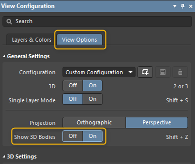
The display of 3D body models in the PCB 3D view is controlled by a setting in the View Configuration Panel. We will take a look at how to ensure this option is enabled.
Starting in Version: 18.0
Up to Version: Current
Solution Details
The 3D model display is controlled by the Show 3D Bodies setting. To show your 3D models, ensure this option is turned on in the View Configuration panel:
View ► Panels ► View Configuration ► View Options ► Show 3D Bodies
For more information on this area of the software, please review the following page in our documentation: https://www.altium.com/documentation/altium-designer/pcb-pnl-viewconfigurationview-configuration-ad
Additional 3D body view control can be performed on the body in the PCB Panel’s 3D Editor section.
In this section, the blue cone controls the visibility of the displayed model. Clicking the cone will toggle through opacity levels, or you can select directly from the drop-down as shown in the image. More information is available here: https://www.altium.com/documentation/altium-designer/pcb-pnl-pcbpcb-3d-models-ad
View ► Panels ► PCB ► 3D Models
The Opacity can also be controlled by the component properties in the Properties panel once the component is selected:
Источник
10 полезных советов по работе в Altium Designer. Часть 4

Продолжение цикла 10 полезных советов на популярные темы, которые помогут вам упростить и ускорить работу с инструментами Altium Designer.
Другие статьи цикла «10 полезных советов по работе в Altium Designer»: часть 1, часть 2, часть 3.
Скрыть 3D-модели
Область применения: редактор плат

Чтобы быстро включать и отключать отображение 3D-моделей при просмотре документа платы в 3D-режиме отображения, используйте сочетание клавиш Shift+Z. Соответствующая опция находится на вкладке View Options в панели View Configuration.
Режимы размещения компонентов
Область применения: редактор плат
 В процессе размещения компонентов на печатной плате можно менять взаимодействие компонентов между собой: нажатие клавишы R в процессе перемещения компонента. 3 режима: Ignore – Игнорировать, Avoid – Избегать, Push – Толкать.
Работа с группами компонентов
Область применения: редакторы электрических схем и печатных плат

Для работы с несколькими наборами объектов одновременно (Например с компонентами на схеме или проводниками на плате) вы можете использовать Selection Memory, который позволяет создавать наборы различных объектов для быстрого доступа к ним через горячие клавиши с использованием цифр 1…8.
Развернуть печатную плату
Область применения: редактор печатных плат

Нажмите последовательно клавиши V-B (Необходимо чтобы была включена английская раскладка клавиатуры) или сочетание клавиш Ctrl+F (Flip Board) чтобы развернуть печатную плату.
Отображение границ зазоров
Область применения: редактор печатных плат

В процессе интерактивной трассировки можно увидеть свободную зону для новых проводников специальной подсветкой. Сочетание клавиш Ctrl + W в процессе трассировки активирует отображение границ объектов с учетом правил проектирования. Подробнее
Способ отображения примитивов
Область применения: редактор печатных плат

Для того чтобы изменить способ восприятия печатной платы и настроить его под свои предпочтения, вы можете скрыть или изменить способ отображения любых примитивов на печатной плате (Доступные режимы: скрыть примитив, только контур, установить прозрачность). На панели View Configurations (Клавиша L) в разделе Object Visibility настраивается способ отображения.
Процент заполнения медью
Область применения: редактор печатных плат

Получить процент заполнения медью для каждого слоя печатной платы можно через панель Properties. Для этого необходимо:
Полярные координаты
Область применения: редактор печатных плат

В основе работы редактора плат лежат сетки – объекты допускается располагать в узлах так называемой сетки привязки. Возможно определение множества сеток привязки, которые можно ограничить только заданной областью, если это необходимо. Сеткам задаются различные приоритеты, и сетка с наивысшим приоритетом, доступная в заданном месте, применяется автоматически. Также действие сеток может быть ограничено компонентами и/или остальными объектами.
Система поддерживает создание пользовательских сеток двух типов:
Работа с хранением файлов
Область применения: Все редакторы
Для работы с резервными копиями файлов платы и системе контроля версий используется панель Storage Manager. В любой момент вы можете выполнить откат к одной из предыдущих версий файла.
Область применения: Редактор электрических схем

Если схемный символ, который вы создаете в библиотеке, имеет несколько режимов представления (Modes), вы можете задать пользовательские имена для альтернативных представлений – для этого используйте команду Tools » Mode » Rename, когда активно нужное альтернативное представление. Подробнее
Доступно с версии Altium Designer 21.
Другие статьи цикла
Заключение
Получить еще больше советов, обсудить вопросы проектирования электроники с использованием инструментов Altium можно в нашем Telegram-канале Altium&Electronics.
Следить за новостями сообщества Altium можно в VK, Facebook и Instagram.
Источник
Настройка и кастомизация рабочего пространства Altium Designer

В статье рассматриваются способы повышения эффективности и комфорта работы инженера при использовании в качестве инструмента для проектирования САПР Altium Designer.
Введение
От чего зависит эффективность и комфорт работы инженера в процессе проектирования нового электронного устройства? От удобства его рабочего места и удобства взаимодействия с инструментами, которые он использует в процессе своей работы. Altium Designer – это один из основных инструментов, с которым работает инженер-проектировщик.
Системные требования
Первое, на что стоит обратить внимание, это соответствие рабочего места рекомендуемым требованиям Altium Designer. Рекомендуемые системные требования к рабочей станции для актуальной версии Altium Designer можно найти в соответствующем разделе документации.

Немаловажным фактором в данном случае является наличие двух мониторов с минимальным разрешением 2560×1440. Поскольку инженеру проектировщику необходимо работать одновременно и с электрической схемой, и печатной платой (используя инструменты перекрестного выбора), в этом случае удобно, если схема расположена на одном мониторе, а плата на втором, либо это может быть параллельная работа с любым другим редактором (оформление чертежей в Draftsman, работа с составом проекта в ActiveBom, работа с производственными файлами в Camtastic и другими).

Еще одним рекомендуемым удобным инструментом рабочего места инженера проектировщика является 3D-манипулятор SpaceMouse®, который позволяет работать с 3D пространством платы. Основное преимущество заключается в том, что повышается скорость навигации по 3D пространству, и появляется унифицированный интерфейс работы с 3D пространством во всех САПР, использующих трехмерный способ отображения, в том числе механические (такие как SolidWorks®) и предназначенные для моделирования (такие как ANSYS®) – нет необходимости помнить и каждый раз вспоминать клавиши для различных САПР для работы с трехмерным пространством.
Настройка проектного пространства
Следующий фактор, это гибкость инструмента и возможность его настройки и конфигурирование под требования инженера. В Altium Designer имеется множество способов настройки и кастомизации проектного пространства чтобы обеспечить более высокую производительность вашей работы.
Когда документ открыт, он становится активным документом в строке документов (Documents Bar) в главном проектном окне. Можно одновременно открыть множество документов, и у каждого открытого документа будет собственная вкладка над проектным окном. В главном проектном окне только один документ может быть активным. Активный документ отличается подсвеченной вкладкой.

Чтобы сделать активным другой открытый документ, щелкните мышью по его вкладке. Либо используйте сочетания клавиш Ctrl+Tab и Ctrl+Shift+Tab для переключения между открытыми документами вперед и назад соответственно. Если у вас открыто большое количество документов, вы можете сгруппировать их, включив параметр Group documents if need в области Documents Bar на странице System — View диалогового окна Preferences.
Диалоговое окно Preferences позволяет выполнять настройку поведения различных редакторов и проектного пространства в зависимости от различных случаев работы с проектом. Рассмотрим самые основные настройки, позволяющие настроить проектное пространство под свои задачи.
Документы могут быть сгруппированы по типу или по проекту. Либо можно отключить группировку и включить отображение документов в несколько строк. Центральной кнопкой мыши можно закрыть любой документ.
Управление окнами документов
Вы не ограничены просмотром лишь одного проектного документа и работой в нем. Доступно множество команд, которые позволяют управлять открытыми документами и настраивать их отображение в соответствии с вашими требованиями.

Щелкните ПКМ по вкладке документа, чтобы открыть различные команды для управления документом. Эти команды включают в себя закрытие и сохранение документов, а также команды, которые влияют на отображение всех открытых документов в главном проектном окне, как показано ниже. Команды для разделения главного проектного окна по вертикали (Split Vertical) или по горизонтали (Split Horizontal) очень полезны при выполнении перекрестных задач между документами, таких как перекрестный переход между схемой и платой. Когда области разделены, работа с ними осуществляется как с отдельными окнами.
Компоновки рабочего стола
Для дальнейшей помощи в настройке рабочего пространства, Altium Designer поддерживает понятие компоновок рабочего стола. Эта возможность позволяет задать расположение окон документов приложения, рабочих панелей и панелей инструментов необходимым образом, а затем сохранить эту компоновку в файл. Благодаря этой возможности, множество пользователей может быстро настроить свое проектное пространство в соответствии со своими предпочтениями путем загрузки компоновок. Команды на сохранение и загрузку компоновок, а также на сброс до компоновки по умолчанию, доступны на странице System — View диалогового окна Preferences.
Кастомизация рабочего пространства
У каждого проектировщика свой стиль работы. Проектное пространство можно очень тонко кастомизировать под свои нужны, чтобы повысить производительность. Например, вы можете создавать новые панели инструментов и команды, а также добавлять команды в панели инструментов и меню, назначать и менять им сочетания клавиш и создавать собственные меню.

В основе работы каждого из элементов лежит предварительно настроенное средство запуска процесса, которое активирует команду при выборе этого элемента. Предварительно настроенные средства запуска процессов (доступ к которым осуществляется через диалоговое окно Edit Command) объединяют в себе процесс, который запускает выбранную команду, а также параметры, изображение (иконку), заголовок (название элемента, которое отображается в ресурсе), описание и связанные с ним сочетания клавиш. При изменении средства запуска процесса будут обновлены все связанные инстанции команды во всех панелях инструментов.

Для кастомизации ресурсов в редакторе, а также для добавления и удаления элементов в этих ресурсах, используется диалоговое окно Customizing Editor. Когда диалоговое окно Customizing Editor открыто, вы можете перетаскивать команды между активными меню и панелями инструментов. Чтобы открыть диалоговое окно, вы можете щелкнуть ПКМ по строке меню или панели инструментов и выбрать команду Customize из контекстного меню либо дважды щелкнуть мышью по пустой (свободной от команд) области строки меню или панели инструментов. У каждого редактора есть собственная версия этого диалогового окна.
Вы можете указать активную (видимую) строку главного меню, выбрав меню из выпадающего списка Bar to use as Main Menu на вкладке Toolbars в диалоговом окне Customizing Editor.
Для создания новой панели инструментов необходимо перейти на вкладку Toolbars диалогового окна Customizing Editor, где вы можете выбрать отображаемое главное меню и панели инструментов, создать новую и продублировать существующую панель инструментов, а также переименовать, удалить или восстановить панель инструментов:

Команду можно связать с панелью инструментов или продублировать при ее добавлении в панель инструментов. Связанная команда будет обновлена при изменении исходного средства запуска процесса. Продублированная команда останется копией изначального средства запуска процесса и не будет изменена. Дублированные команды могут быть изменены для создания новой команды путем изменения свойств средства запуска процесса. Чтобы добавить команду в панель инструментов, необходимо:
Создание своей команды
Для этого на вкладке Commands диалогового окна Customizing Editor нажмите New, чтобы открыть диалоговое окно Edit Command.
Нажмите кнопку Browse, чтобы открыть диалоговое окно Process Browser для выбора нужного процесса новой команды: PCB:SetupPreferences.
Используйте элементы управления диалогового окна Process Browser, чтобы найти нужный процесс, затем нажмите OK, чтобы вернуться в диалоговое окно Edit Command.
Также можно ввести дополнительный параметр для команды: OnlineDRC = Toggle.
В диалоговом окне Edit Command запись Caption станет названием команды в соответствующем меню. Используйте название, которое позволит легко распознать новую команду: Toggle OnlineDRC.
Если со средством запуска нового процесса нужно связать изображение, нажмите в поле Bitmap File, чтобы найти файл изображения. Это изображение (или иконка) будет отображаться, когда новая команда будет добавлена в панели инструментов. Например, команда Zoom In использует изображение Zoomin.bmp, которое находится в папке SystemButtons установки Altium Designer.
Если нужно, вы можете использовать область Shortcuts, чтобы добавить основное (Primary) и дополнительное (Alternative) сочетание клавиш.
После определения новой команды нажмите OK.
В область Categories диалогового окна Customizing Editor будет добавлена категория [Custom]. При ее выборе, в области Commands будет отображена новая команда.
Теперь вы можете добавить новую команду в подходящие панели инструментов. Для получения более подробной информации перейдите в раздел Добавление команд в панели инструментов и меню документации.
Создание выпадающего меню

Категория [System Level] на вкладке Commands диалогового окна Customizing Editor включает в себя команды для переключения видимости плавающих панелей и переключения фокуса между плавающими панелями. Новые команды, добавленные в эту категорию, станут системными командами, и их сочетания клавиш можно будет использовать в любом редакторе.
В режиме кастомизации появляется доступ к спискам сочетаний клавиш для текущего редактора и для различных всплывающих меню, которые также можно добавлять, создавать, удалять и изменять таким же образом, что и меню и панели инструментов.
Для редактора может быть активной только одна таблица сочетаний клавиш. Например, Schematic Shortcuts является названием по умолчанию для таблицы сочетаний клавиш редактора схем. Если сочетание клавиш изменяется в команде, оно автоматически изменяется в активной таблице.
Перенос и резервирование настроек и кастомизации
Было бы плохо, если бы все настройки и кастомизацию невозможно было бы резервировать и приходилось бы делать каждый раз заново, когда вы меняете рабочее место, например с рабочего на домашнее удаленное, либо вашу рабочую станцию сдали в ремонт и вы хотите поработать на рабочей станции вашего коллеги который сейчас в отпуске.
Altium Designer также имеет встроенное решение для резервного копирования и восстановления основных файлов с помощью одной кнопки.
Сохранение резервных копий настроек и кастомизации возможна как в файл, так и на сервер управляемых данных (Altium Concord Pro или Altium 365 Workspace).
Если проекты также расположены на сервере управляемых данных, то переход с одной рабочей станции на другую может занимать совсем немного времени.
Типовая процедура восстановления файла настроек выглядит следующим образом:
Заключение
Получить еще больше информации по эффективной работе с Altium Designer, обсудить вопросы проектирования электроники с использованием инструментов Altium, можно в нашем Telegram-канале Altium&Electronics.
Следить за новостями сообщества Altium можно в VK, Facebook и Instagram.
Источник
Aleksey_75 (10.01.2016 11:43, просмотров: 4452)

Подскажите по 3D в Altium делаю библиотеку, создал футпринт, с http://www.3dcontentcentral.com/ скачал модель в step, разместил, зажимаю шифт , появляется кург, при любой попытке вращения выдает “action not available in 3d” Куда рыть ???
-
- Есть видеоуроки неплохие. Harry(67 знак., 10.01.2016 21:49, ссылка, ссылка)
- Крутить правой кнопкой мыши с зажатым шифтом – JackI(10.01.2016 18:01)
- все так делаю, реакции нет – Aleksey_75(10.01.2016 19:07)
- Здесь почитать, вроде аналогичное было -> – Make_Pic(10.01.2016 16:45, ссылка)
- Увы, там уже был, ничего внятного. Aleksey_75(119 знак., 10.01.2016 17:10)
- Если поточнее, то для вращения платы – Shift+ПРАВАЯ клавиша мыши Make_Pic(401 знак., 10.01.2016 23:22 – 23:24)
- блин! Точно, Правая кнопка! Работает спс – aleksey_75(11.01.2016 08:01)
- Если поточнее, то для вращения платы – Shift+ПРАВАЯ клавиша мыши Make_Pic(401 знак., 10.01.2016 23:22 – 23:24)
- Увы, там уже был, ничего внятного. Aleksey_75(119 знак., 10.01.2016 17:10)
Created: March 25, 2021 | Updated: May 19, 2023

The display of 3D body models in the PCB 3D view is controlled by a setting in the View Configuration Panel. We will take a look at how to ensure this option is enabled.
Starting in Version: 18.0
Up to Version: Current
Solution Details
The 3D model display is controlled by the Show 3D Bodies setting. To show your 3D models, ensure this option is turned on in the View Configuration panel:
View ► Panels ► View Configuration ► View Options ► Show 3D Bodies
Was this article helpful?
Found an issue with this document? Highlight the area, then use Ctrl+Enter to report it.
We’re sorry to hear the article wasn’t helpful to you.
Could you take a moment to tell us why?
You are reporting an issue with the following selected text
and/or image within the active document:
