Расчет реактивной мощности реактора
В данном примере требуется определить реактивную мощность, потребляемую токоограничивающим реактором с одной обмоткой типа РТСТ-10-1600-0,35-У3.
Исходные данные:
- Uн = 10 кВ – номинальное напряжение;
- Sном = 16000 кВА – номинальная мощность трансформатора типа ТДН-16000/110-У1;
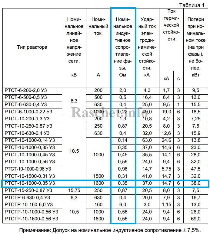
- х = 0,35 Ом – номинальное индуктивное сопротивление реактора, согласно каталога, см. таблицу 1;
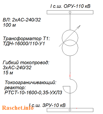
Поясняющая схема представлена ниже.
Расчет
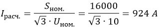
1. Определяем расчетный ток реактора, исходя из мощности трансформатора типа ТДН-16000/110-У1:
2. Определяем индуктивность реактора, зная индуктивное (реактивное) сопротивление [Л2, с.20]:
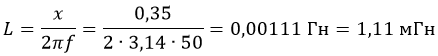
где: ω = 2πf = 314 – угловая скорость.
3. Определяем реактивную мощность, потребляемую реактором по формуле 26 [Л1, с.42]:

где:
- Р, U и cosϕ – параметры сети;
- L и х – индуктивность и реактивное сопротивление реактора.
Читать еще: «Выбор токоограничивающих реакторов с одной обмоткой».
Литература:
- Реактивная мощность (2-е издание) Минин Г.П. 1978 г.
- Справочная книга электрика. Григорьева В.И. 2004 г.
Всего наилучшего! До новых встреч на сайте Raschet.info.
реактивная мощность реактора, реактор, РТСТ
Благодарность:
Если вы нашли ответ на свой вопрос и у вас есть желание отблагодарить автора статьи за его труд, можете воспользоваться платформой для перевода средств «WebMoney Funding» и «PayPal».
Данный проект поддерживается и развивается исключительно на средства от добровольных пожертвований.
Проявив лояльность к сайту, Вы можете перечислить любую сумму денег, тем самым вы поможете улучшить данный сайт, повысить регулярность появления новых интересных статей и оплатить регулярные расходы, такие как: оплата хостинга, доменного имени, SSL-сертификата, зарплата нашим авторам.
Мощность
реактора
определяется энерговыделением в единицу
времени в его активной зоне.
В свою
очередь, скорость энерговыделения
зависит от числа делений ядер топлива
и, следовательно, плотности потока
тепловых нейтронов, вызывающих эти
деления.
Мощность
реактора связана со средней плотностью
потока тепловых нейтронов соотношением:
![]()
где
N
— мощность реактора, кВт;
Фт
— средняя плотность потока тепловых
нейтронов в топливе, н/(см2
-с);
af
—
эффективное сечение деления 2
3 5
U,
см2;
N5
– концентрация ядер 2
35
U,
см-1;
V
– объем активной зоны, см3.
Кампания
реактора —
это время, в течение которого активная
зона может работать на номинальной
мощности с одной и той же загрузкой.
Определяется кампания запасом
реактивности и кончается при полном
удалении из активной зоны борной кислоты,
когда цепная реакция прекращается.
Способность
реактора выработать за время кампании
определенное количество энергии
характеризует его энергоресурс
(энергозапас)
– QK.
Использованную часть энергоресурса
называют энерговыработкой
реактора.
Если
реактор в течение определенного времени
работал на различных уровнях мощности,
то его энерговыработка Qвыр
равна сумме энерговыработок на каждом
уровне мощности.
Кампанию
и энергоресурс реактора иногда выражают
в эффективных
сутках,
т. е. в сутках работы на номинальной
мощности. Одни эффективные сутки для
ВВЭР-1000 соответствуют энерговыработке
3000*24 = 72 ГВт*сут. Для перевода энерговыработки
в эффективные сутки следует использовать
соотношение:

Количество
загруженного делящегося топлива в
ядерном реакторе при его работе непрерывно
уменьшается за счет деления ядер 235U
и радиационного захвата ими нейтронов.
Этот процесс называют
выгоранием
топлива.
Выгорание
связано с энерговыработкой линейной
зависимостью:
mвыг5
= 1,23 • N
t
где
твыг
— масса выгоревшего 235U,
г; 1,23 — расход топлива в граммах,
соответствующий энерговыработке в 1
МВт•сут, с учетом потерь энергии,
радиационного захвата нейтронов и
деления 235U;
N
— мощность
реактора, МВт;
t,
— время работы реактора на мощности N,
сут.
Основная
часть расхода топлива определяется
количеством разделившихся ядер 235U
за определенное время работы реактора
на мощности. Масса разделившихся ядер
в граммах за время t
работы реактора на мощности N,
т.е. при энерговыработке Q
= Nt,
равна
m5дел
= 1,05 • Nt
= 1,05 Q,
где
1,05 — масса 235U
в граммах, разделившегося при
энерговыработке 1 МВт • сут.
В
связи с выгоранием 235U
уменьшается кэф,
а следовательно, реактивность и запас
реактивности. Изменение запаса
реактивности за счет выгорания —
длительный процесс. Он зависит только
от энерговыработки реактора.
Воспроизводство
и отравление
При
работе ядерного реактора постепенно
исчезают ядра загруженного топлива
и появляются новые. Среди них делящиеся
ядра 239Ри,
241Ри.
Процесс накопления последних называется
воспроизводством
делящегося
материала.
При
делении топлива образуется около
200
нуклидов — продуктов (осколков)
деления.
Некоторые
ядра, образующиеся при делении урана и
плутония, имеют большие сечения поглощения
тепловых нейтронов.
IIoглощение
нейтронов теми из них, сечение поглощения
которых очень велико, а концентрация
которых сравнительно быстро достигает
равновесной, называется отравлением
реактора.
Основная
масса образующихся ядер, называемая
шлаками, имеет сечение поглощения
тепловых нейтронов не больше, чем сечение
деления топлива.
В
процессе накопления шлаков (при работе
реактора) запас реактивности уменьшается.
Это
уменьшение запаса реактивности вследствие
поглощения тепловых нейтронов шлаками
называется шлакованием
реактора.
Процесс
шлакования так же, как и выгорания,
медленный, связанный только с кампанией
(энергонаработкой) реактора.
При
эксплуатации реактора разделить процессы
выгорания и шлакования невозможно.
Соседние файлы в предмете [НЕСОРТИРОВАННОЕ]
- #
- #
- #
- #
- #
- #
- #
- #
- #
- #
- #
There is a direct proportionality between the neutron flux and the reactor thermal power in each nuclear reactor. The term thermal power is usually used because it means the rate at which heat is produced in the reactor core due to fissions in the fuel. Nuclear power plants also use the total output of electrical power. Still, this value is due to the efficiency of conversion (usually from 30% to 40%) always being smaller than the reactor’s thermal power. Typical reactor nominal thermal power is about 3400MW, thus corresponding to the net electric output of 1100MW. Therefore the typical thermal efficiency of its Rankine cycle is about 33%.

In previous chapters, we have solved diffusion equations for various shapes of reactors. For example, the solution for a finite cylindrical reactor is:

where Bg2 is the total geometrical buckling.
It must be added there are constants A and C that cannot be obtained from the diffusion equation because these constants give the absolute value of neutron flux or the reactor power.
There is a direct proportionality between the neutron flux and the reactor thermal power in each nuclear reactor. The term thermal power is usually used because it means the rate at which heat is produced in the reactor core due to fissions in the fuel. Nuclear power plants also use the total output of electrical power. Still, this value is due to the efficiency of conversion (usually from 30% to 40%) always being smaller than the reactor’s thermal power.
Back to the proportionality between the neutron flux and the reactor thermal power.
Reaction Rate
Knowledge of the neutron flux (the total path length of all the neutrons in a cubic centimeter in a second) and the macroscopic cross-sections (the probability of having an interaction per centimeter path length) allows us to compute the rate of interactions (e.g.,, rate of fission reactions). This reaction rate (the number of interactions taking place in that cubic centimeter in one second) is then given by multiplying them together:

where:
Ф – neutron flux (neutrons.cm-2.s-1)
σ – microscopic cross-section (cm2)
N – atomic number density (atoms.cm-3)
The reaction rate for various types of interactions is found from the appropriate cross-section type:
- Σt . Ф – total reaction rate
- Σa . Ф – absorption reaction rate
- Σc . Ф – radiative capture reaction rate
- Σf . Ф – fission reaction rate
To determine the thermal power, we have to focus on the fission reaction rate. For simplicity, let assume that the fissionable material is uniformly distributed in the reactor. In this case, the macroscopic cross-sections are independent of position. Multiplying the fission reaction rate per unit volume (RR = Ф . Σ) by the total volume of the core (V) gives us the total number of reactions occurring in the reactor core per unit time. But we also know the amount of energy released per one fission reaction to be about 200 MeV/fission. Now, it is possible to determine the energy release rate (power) due to the fission reaction. The following equation gives it:
P = RR . Er . V = Ф . Σf . Er . V = Ф . NU235 . σf235 . Er . V
where:
P – reactor power (MeV.s-1)
Ф – neutron flux (neutrons.cm-2.s-1)
σ – microscopic cross section (cm2)
N – atomic number density (atoms.cm-3)
Er – the average recoverable energy per fission (MeV / fission)
V – total volume of the core (m3)
Energy Released per Fission
See also: Energy Released per Fission
The total energy released in fission can be calculated from binding energies of the initial target nucleus to be fissioned and binding energies of fission products. But not all the total energy can be recovered in a reactor. For example, about 10 MeV is released in the form of neutrinos (in fact, antineutrinos). Since the neutrinos are weakly interacting (with an extremely low cross-section of any interaction), they do not contribute to the energy that can be recovered in a reactor.
The total energy released in a reactor is about 210 MeV per 235U fission, distributed as shown in the table. In a reactor, the average recoverable energy per fission is about 200 MeV, being the total energy minus the energy of antineutrinos that are radiated away. This means that about 3.1⋅1010 fissions per second are required to produce a power of 1 W. Since 1 gram of any fissile material contains about 2.5 x 10²¹ nuclei, the fissioning of 1 gram of fissile material yields about 1 megawatt-day (MWd) of heat energy.
As can be seen from the description of the individual components of the total energy released during the fission reaction, there is a significant amount of energy generated outside the nuclear fuel (outside fuel rods). Especially the kinetic energy of prompt neutrons is largely generated in the coolant (moderator). This phenomenon needs to be included in the nuclear calculations.
For LWR, it is generally accepted that about 2.5% of total energy is recovered in the moderator. This fraction of energy depends on the materials, their arrangement within the reactor, and thus on the reactor type.

Example – Reaction Rate and Reactor Power
A typical thermal reactor contains about 100 tons of uranium with an average enrichment of 2% (do not confuse it with the enrichment of the fresh fuel). If the reactor power is 3000MWth, determine the reaction rate and the average core thermal flux.
Solution:
The amount of fissile 235U per the volume of the reactor core.
m235 [g/core] = 100 [metric tons] x 0.02 [g of 235U / g of U] . 106 [g/metric ton]
= 2 x 10⁶ grams of 235U per the volume of the reactor core
The atomic number density of 235U in the volume of the reactor core:
N235 . V = m235 . NA / M235
= 2 x 10⁶ [g 235 / core] x 6.022 x 10²³ [atoms/mol] / 235 [g/mol]
= 5.13 x 1027 atoms / core
The microscopic fission cross-section of 235U (for thermal neutrons):
σf235 = 585 barns
The average recoverable energy per 235U fission:
Er = 200.7 MeV/fission

Zero Power Criticality vs. Power Operation
The neutron flux can have any value, and the critical reactor can operate at any power level. It should be noted the flux shape derived from the diffusion theory is only a hypothetical case in a uniform homogeneous cylindrical reactor at low power levels (at “zero power criticality”).
In the power reactor core at power operation, the neutron flux can reach, for example, about 3.11 x 10¹³ neutrons.cm-2.s-1, but this value depends significantly on many parameters (type of fuel, fuel burnup, fuel enrichment, position in fuel pattern, etc.). The power level does not influence the criticality (keff) of a power reactor unless thermal reactivity feedbacks act (operation of a power reactor without reactivity feedbacks is between 10E-8% – 1% of rated power).
At power operation (i.e., above 1% of rated power), the reactivity feedbacks cause the flattening of the flux distribution because the feedbacks acts stronger on positions where the flux is higher. The neutron flux distribution in commercial power reactors depends on many other factors such as the fuel loading pattern, control rods position, and it may also oscillate within short periods (e.g.,, due to the spatial distribution of xenon nuclei). There is no cosine and J0 in the commercial power reactor at power operation.
See also: Nuclear Reactor as the Antineutrino Source.
Reactivity Feedbacks
In an operating power reactor the neutron population is always large enough to generated heat. It is the main purpose of power reactors to generate a large amount of heat. This causes the system’s temperature to change and material densities to change as well (due to the thermal expansion).
Because macroscopic cross-sections are proportional to densities and temperatures, the neutron flux spectrum also depends on the density of the moderator. These changes, in turn, will produce some changes in reactivity. These changes in reactivity are usually called reactivity feedbacks and are characterized by reactivity coefficients. This is a very important area of reactor design because the reactivity feedbacks influence the stability of the reactor. For example, reactor design must assure that under all operating conditions, the temperature feedback will be negative.
The reactivity coefficients that are important in power reactors (PWRs) are:
- Moderator Temperature Coefficient – MTC
- Fuel Temperature Coefficient or Doppler Coefficient
- Pressure Coefficient
- Void Coefficient
As can be seen, there are not only temperature coefficients that are defined in reactor dynamics. In addition to these coefficients, there are two other coefficients:
- Total Power Coefficient
- Boron Coefficient
The total power coefficient is the combination of various effects and is commonly used when reactors are at power conditions. It is because, at power conditions, it is difficult to separate the moderator effect from the fuel effect and the void effect as well. All these coefficients will be described in the following separate sections. The reactivity coefficients are of importance in the safety of each nuclear power plant which is declared in the Safety Analysis Report (SAR).
Example: Power increase – from 75% up to 100%
The temperature, pressure, or void fraction change during any power increase, and the core’s reactivity changes accordingly. It is difficult to change any operating parameter and not affect every other property of the core. Since it is difficult to separate all these effects (moderator, fuel, void, etc.), the power coefficient is defined. The power coefficient combines the Doppler, moderator temperature, and void coefficients. It is expressed as a change in reactivity per change in percent power, Δρ/Δ% power. The value of the power coefficient is always negative in core life. Still, it is more negative at the end of the cycle primarily due to the decrease in the moderator temperature coefficient.
Let us assume that the reactor is critical at 75% of rated power and that the plant operator wants to increase power to 100% of rated power. The reactor operator must first bring the reactor supercritical by inserting a positive reactivity (e.g.,, by control rod withdrawal or boron dilution). As the thermal power increases, moderator temperature and fuel temperature increase, causing a negative reactivity effect (from the power coefficient), and the reactor returns to the critical condition. Positive reactivity must be continuously inserted (via control rods or chemical shim) to keep the power to be increasing. After each reactivity insertion, the reactor power stabilizes itself proportionately to the reactivity inserted. The total amount of feedback reactivity that must be offset by control rod withdrawal or boron dilution during the power increase (from ~1% – 100%) is known as the power defect.
Let assume:
- the power coefficient: Δρ/Δ% = -20pcm/% of rated power
- differential worth of control rods: Δρ/Δstep = 10pcm/step
- worth of boric acid: -11pcm/ppm
- desired trend of power decrease: 1% per minute
75% → ↑ 20 steps or ↓ 18 ppm of boric acid within 10 minutes → 85% → next ↑ 20 steps or ↓ 18 ppm within 10 minutes → 95% → final ↑ 10 steps or ↓ 9 ppm within 5 minutes → 100%

Thermal Power and Power Distribution
The power distribution significantly changes also with changes in the thermal power of the reactor. During power changes at power operation mode (i.e., from about 1% up to 100% of rated power), the temperature reactivity effects play a very important role. As the neutron population increases, the fuel and the moderator increase their temperature, which results in a decrease in reactivity of the reactor (almost all reactors are designed to have the temperature coefficients negative). The negative reactivity coefficient acts against the initial positive reactivity insertion, and this positive reactivity is offset by negative reactivity from temperature feedbacks.
This effect naturally occurs on a global scale and also on a local scale.
During thermal power increase, the effectiveness of temperature feedbacks will be greatest where the power is greatest. This process causes the flattening of the flux distribution because the feedbacks acts stronger on positions where the flux is higher.
It must be noted, the effect of change in the thermal power has significant consequences on the axial power distribution.
In reality, when there is a change in the thermal power, and the coolant flow rate remains the same, the difference between inlet and outlet temperatures must increase. It follows from the basic energy equation of reactor coolant, which is below:
P=↓ṁ.c.↑∆t

The inlet temperature is determined by the pressure in the steam generators. Therefore the inlet temperature changes minimally during the change of thermal power. It follows the outlet temperature must change significantly as the thermal power changes. When the inlet temperature remains almost the same and the outlet changes significantly, it stands to reason, the average temperature of coolant (moderator) will also change significantly. It follows the temperature of the top half of the core increases more than the temperature of the bottom half of the core. Since the moderator temperature feedback must be negative, the power from the top half will shift to the bottom half. In short, the top half of the core is cooled (moderated) by hotter coolant, and therefore it is worse moderated. Hence the axial flux difference, defined as the difference in normalized flux signals (AFD) between the top and bottom halves of a two-section excore neutron detector, will decrease.
AFD is defined as:
AFD or ΔI = Itop – Ibottom
where Itop and Ibottom are expressed as a fraction of rated thermal power.
Types of Reactor Power
In general, we have to distinguish between three types of power outputs in power reactors.
- Nuclear Power. Since the thermal power produced by nuclear fissions is proportional to neutron flux level, the most important is a measurement of the neutron flux from the reactor safety point of view. The neutron flux is usually measured by excore neutron detectors, which belong to the so-called excore nuclear instrumentation system (NIS). The excore nuclear instrumentation system monitors the reactor’s power level by detecting neutron leakage from the reactor core. The excore nuclear instrumentation system is considered a safety system because it provides inputs to the reactor protection system during startup and power operation. This system is of the highest importance for reactor protection systems because changes in the neutron flux can be almost promptly recognized only via this system.
- Thermal Power. Although nuclear power provides a prompt response to neutron flux changes and is an irreplaceable system, it must be calibrated. The accurate thermal power of the reactor can be measured only by methods based on the energy balance of the primary circuit or the energy balance of the secondary circuit. These methods provide accurate reactor power, but these methods are insufficient for safety systems. Signal inputs to these calculations are, for example, the hot leg temperature or the flow rate through the feedwater system, and these signals change very slowly with neutron power changes.
- Electrical Power. Electric power is the rate at which the generator generates electrical energy. For example, for a typical nuclear reactor with thermal power of 3000 MWth, about ~1000MWe of electrical power is generated in the generator.
References:
Nuclear and Reactor Physics:
- J. R. Lamarsh, Introduction to Nuclear Reactor Theory, 2nd ed., Addison-Wesley, Reading, MA (1983).
- J. R. Lamarsh, A. J. Baratta, Introduction to Nuclear Engineering, 3d ed., Prentice-Hall, 2001, ISBN: 0-201-82498-1.
- W. M. Stacey, Nuclear Reactor Physics, John Wiley & Sons, 2001, ISBN: 0- 471-39127-1.
- Glasstone, Sesonske. Nuclear Reactor Engineering: Reactor Systems Engineering, Springer; 4th edition, 1994, ISBN: 978-0412985317
- W.S.C. Williams. Nuclear and Particle Physics. Clarendon Press; 1 edition, 1991, ISBN: 978-0198520467
- Kenneth S. Krane. Introductory Nuclear Physics, 3rd Edition, Wiley, 1987, ISBN: 978-0471805533
- G.R.Keepin. Physics of Nuclear Kinetics. Addison-Wesley Pub. Co; 1st edition, 1965
- Robert Reed Burn, Introduction to Nuclear Reactor Operation, 1988.
- U.S. Department of Energy, Nuclear Physics and Reactor Theory. DOE Fundamentals Handbook, Volume 1 and 2. January 1993.
Advanced Reactor Physics:
- K. O. Ott, W. A. Bezella, Introductory Nuclear Reactor Statics, American Nuclear Society, Revised edition (1989), 1989, ISBN: 0-894-48033-2.
- K. O. Ott, R. J. Neuhold, Introductory Nuclear Reactor Dynamics, American Nuclear Society, 1985, ISBN: 0-894-48029-4.
- D. L. Hetrick, Dynamics of Nuclear Reactors, American Nuclear Society, 1993, ISBN: 0-894-48453-2.
- E. E. Lewis, W. F. Miller, Computational Methods of Neutron Transport, American Nuclear Society, 1993, ISBN: 0-894-48452-4.
See above:
Diffusion Theory
Мощность – реактор
Cтраница 1
Мощность реактора регулируют, изменяя величину р, поэтому р обычно является функцией времени. Число групп т, как правило, равно 6 – 10, иногда более ( в зависимости от типа реактора), в связи с чем классическое решение системы этих уравнений представляет собой сложную задачу. Система уравнений характеризует кинетику реактора только при упрощающих предположениях, однако для большинства практических случаев применения достигаемая точность вполне достаточна.
[1]
Мощность реакторов здесь также доведена до 36 тыс. т / год.
[2]
Мощность реактора может быть выраженз в ваттах, киловаттах или мегаваттах. Между мощностью, средним потоком нейтронов и объемом реактора существует непосредственная связь.
[3]
Мощность реактора в значительной степени зависит от его системы охлаждения. В этом заключается особенность ядерных реакторов как источников энергии. Мгновенная мощность определяется числом атомов, подвергающихся делению за 1 сек. В некоторых реакторах достаточно удалить управляющие стержни, чтобы возникла цепная реакция, а для стабилизации реакции ( когда достигнут определенный уровень) снова ввести стержни в реактор. При этом, естественно, предполагается, что материалы, из которых построен реактор, хорошо выдерживают ту температуру, которая там может возникнуть, причем это зависит лишь от эффективности системы охлаждения.
[4]
Мощность реактора как генератора пара определяется количеством каналов и мощностью каждого из них. При данных параметрах каналов паро-производительность реактора-парогенератора зависит от числа каналов. Чем их больше, тем выше паро – производительность, однако усложняется конструкция установки и ее эксплуатация.
[5]
Мощность реактора изменяется от номинальной до мощности холостого хода менее чем за 2 с. Обмотки переменного тока каждой фазы располагаются на двух вертикальных стержнях отдельного сердечника.
[7]
Мощность реакторов Qp0, предназначаемых для регулирования напряжения на промежуточной подстанции, равна сумме реактивных мощностей концов участка, примыкающих к подстанции.
[8]
Мощность реакторов промежуточных компенсирующих пунктов КП равна сумме стоков реактивных мощностей концов участков, примыкающих к КП.
[9]
Мощность реактора автоматически регулируется с помощью устройств автоматического пуска и регулирования температуры и мощности. Устройство автоматического пуска предназначено для автоматического пуска реактора до 0 1 % и регулирования мощности от ОД до 10 % номинального значения.
[11]
Мощность реактора 1000 МВт, он работает в блоке с двумя турбинами типа К-500-65 / 3000 по 500 МВт каждая.
[12]
Мощность реактора регулируется при помощи специальных регулирующих стержней PC, которые содержат элементы, поглощающие нейтроны.
[13]
Мощность реактора автоматически регулируется с помощью двух устройств: автопуска и регулирования температуры и мощности.
[14]
Найдите мощность реактора, в котором делится 1 г 235U в сутки.
[15]
Страницы:
1
2
3
4
